26. Load
combination with the flood force
The flood force has been applied to the bridge together
with the permanent loads, assuming for both these loads a factor of 1.0,
to the load combinations used in the F.E. model of the phase A.
The flood force was applied according to the steps and
sub-steps listed below. The first and the second steps consist of one
sub-step each, while the other steps were divided into two steps each.
|
load force |
|
% |
Load
Step |
Sub
Step |
|
100% Dead weight |
1 |
1 |
|
Flood force C
Q=1500 |
2 |
2 |
|
Flood force C
Q=1750 |
3 |
4 |
|
Flood force C
Q=2000 |
4 |
6 |
|
Flood force C
Q=2250 |
5 |
8 |
|
Flood force C
Q=2500 |
6 |
10 |
The flood force acts in the
horizontal plane, in the weakest plane of the bridge.
The flood produces a total
shear much higher than the shear produced by the seismic actions, but the
stresses and strains are lower than those produced by the earthquake,
because the flood force is concentrated prevalently on the lateral sides
of the bridge.
The following figure shows
the load-displacement diagram, obtained for the joints at the crown of the
arch.
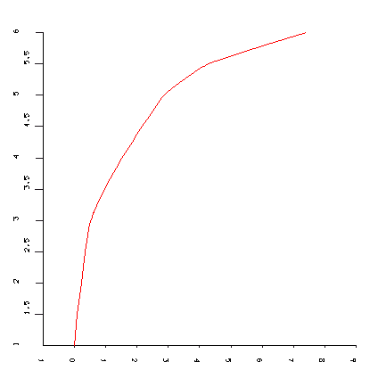
Load-displacement
diagram with the Load-Steps (vertical axis) and
displacements (horizontal
axis) in the Z direction (in 10-1 cm)
Up to the load step no. 3
(flood of 1750 m3 / s) the bridge has a linear behaviour, later
the overall stiffness reduces, with a hardening branch up to the load step
no. 5 (flood of Q = 2250 m3 / s). The inclination of the
diagram changes again and there is another branch of plastic-hardening up
to the load step no. 6 (flood of 2500 m3 / s).
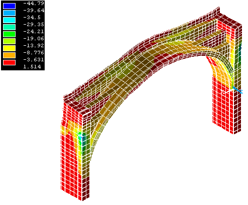
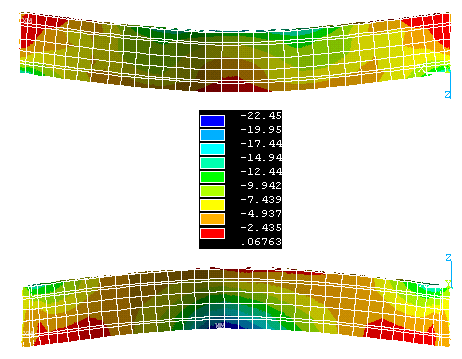
The following figures show the
principal stresses S1, S2 and S3.
S3 Assonometric view at the load step no. 2 (Q = 1500 m3
/ s)
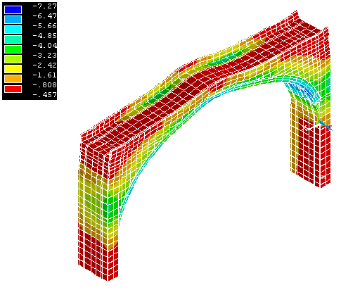
S3 Assonometric view at the load step no. 3 (Q = 1750 m3
/ s)
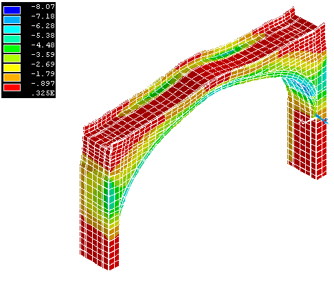
S3 Assonometric view at the load step no. 4 (Q = 2000 m3
/ s)
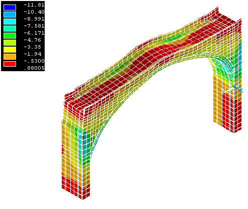
S3 Assonometric view at the load step no. 5 (Q = 2250 m3
/ s)
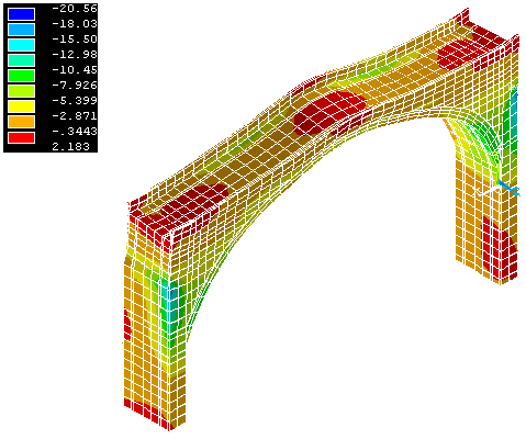
S3 Assonometric view at the load step no. 6 (Q = 2500 m3
/ s)

S3 Assonometric view at the load step no. 6 (Q = 2500 m3
/ s)
S3 Extrados and intrados at the load step no. 6 (Q = 2500
m3 / s)
The main results are:
the stresses and strains are not worrying up to Q =
2000 m3 / s; at the crown of the arch, the compression induced
by the dead weight higher than the tractions induced by the flood. The
tractions at the crown section arise only for Q = 2250 m3 / s.
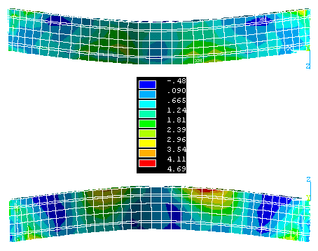
The following figures show the
principal stresses S2 and S1 (in Kg/cmq).
S2 Vista Estradosso (in alto) e Intradosso (in basso) al
passo - Load Steps6 (Q = 2500 m3 /
s)
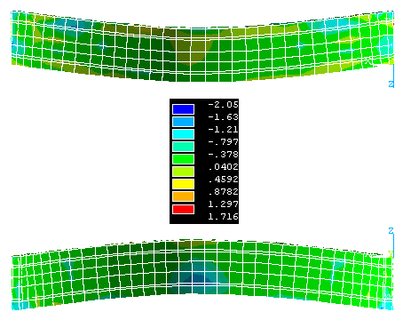
S1 Vista Estradosso (in alto) e Intradosso (in basso) al
passo - Load Steps6 (Q = 2500 m3 /
s)
|