In the second stage the Ansys calculation code was
adopted. This programme enables to perform non-linear analyses of the
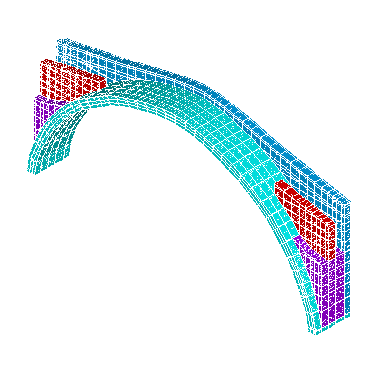
structure. The F.E. model has been created with the available data.
I. Modelling of non-linear
material behaviour:
The brittle behaviour of masonry has been modelled
through an appropriate failure criterion, here defined by means of only
two material parameters ft (uniaxial tensile strength) and fc
(uniaxial compressive strength); cross section of the assumed failure
surface will be defined with a cyclic symmetry about each 120° sector of
the deviatoric plane. Both cracking and crushing failure modes have been
accounted for. The presence of a crack at an integration point has been
represented through modification of the stress-strain relations by
introducing a plane of weakness in a direction normal to the crack face.
Also, a shear transfer coefficient ß has been introduced (depending on
the crack status. open -ßt- or re-closed -ßc-),
representing a shear strength reduction factor for those subsequent loads
inducing sliding (shear) across the crack face.
II. Rate independent plasticity:
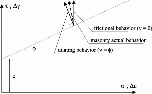
Frictional and dilating behaviour of masonry
In order to reduce the number of the parameters
employed to represents the non-linear behaviour of masonry; a
Drucker-Prager perfectly plastic criterion has been employed in the model,
avoiding the need for definition of a hardening rule. In this way cohesion
c and angle of internal friction f has been
assumed, as the only two material parameters required defining the yield
surface. A non-associated flow rule has been adopted for determining the
direction of plastic straining, which has been calculated assuming the
angle of dilitancy n instead of the angle of
internal friction. The dilitancy (which represents a third material
parameter) controls both the volumetric expansion during the plastic
straining and its deviation from the associated flow rule, the correct
setting of the dilitancy value, moreover, permits to define the relevance
of the frictional behaviour of the material, as n
= 0° signifies a pure frictional behaviour with no volume change during
the plastic flow, while n = f
indicates a purely dilating or perfectly plastic material with zero
friction and the validity of the flow rule. Several ways are possible in
order of representing relationships between f
and n (see f. i. Bishop (1950), Rowe (1962) and
Davis (1968)), focusing the major attention on the physical meaning of the
parameters, as represented in Fig. A, where the trace of the yield
function is depicted in a meridian plane in the t
- s stress space.

fig. A - Frictional and dilating behaviour:
flow rule for masonry material
III. Failure surface
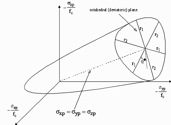
The failure criterion has been adopted (William and
Warnke (1975)), initially defined for concrete, accounts for both cracking
and crushing failure modes trough a smeared model. Despite the need for
five constants in order to define the criterion, in most practical cases
(thereby when the hydrostatic stress is limited by  fc,)
the adopted failure surface has been specified by means of the only two
constants: ft and fc (respectively the uniaxial
tensile and compressive strength). The failure surface that has been
adopted is depicted in Fig. B.

fig. B - Failure surface
IV. References
ANSYS (1993) Revision 5.0A, Swanson Analysis System,
Inc., Houston.
Bishop, AW, (1950) Discussion on measurement of the
shear strength of soils. Geotechnique, Vol. 2, No. 1, pp. 113 -116.
Davis, E.H., (1968) Theories of plasticity and the
failure of soil masses, in I.K. Lee (Editor), Soil mechanics: selected
topics. Butterworth, London, pp. 341-380.
Rowe, P.W., (1962) The stress-dilitancy relation for
static equilibrium of an assembly of particles in contact. Proc. R. Soc.
London, Ser. A, 269, pp. 500-527.
William, K.J., Warnke, E.D., (1975) Constitutive model
for the triaxial behaviour of concrete , Proc. Int. Ass. for Bridge and
Struct. Engng., Vol. 19, ISMES, Bergamo, pp. 174-186.
First a linear analysis was performed, obtaining a
thrust line similar to the one found before in the F.E. model of the arch
alone, but less eccentric.
The tensile stresses were very limited because the
solid modelling allowed for taking into account also the contribution of
the other elements (spandrels, slab) to the bearing mechanism. The solid
model provided a better description of the stress patterns within each
section than the beam model. A non-symmetrical stress pattern has been
obtained, which confirms that the bridge has acquired a non symmetrical
configuration due to the settlements of its foundations and the settlement
of the centering.
The linear analyses were performed taking into account
a maximum tensile stress of 0,5 kg/cm2 in the masonry. This
means that in the regions were the tensile stresses were over this limit,
the finite elements were separated to simulate the formation of cracks.
With this operation the linear analyses performed allow for taking into
account, with a good approximation, the non-linear behaviour of the
masonry.
The analyses under the permanent loads, the live loads
and the thermal actions were performed in the linear field, but the model
connectivity was modified according to the stress pattern present in the
model: in the regions where the stresses were higher than the prefixed
limit of 0,5 kg/cm2 the elements were disconnected or the
external restraints were removed. Therefore, for each load combinations,
different mesh disconnections and restraint conditions were defined.
On the contrary non-linear analyses were performed
under the flood loads and the earthquake actions.
For these analyses a different F.E. model was created,
reducing the elements of the abutments and increasing the limit traction
to improve the convergence of the non-linear analyses. The results
obtained show that the maximum tensile stresses do not concern the main
arch.
